Flow Measurement Instruments
- Low Flow Liquid Meters
- Low Flow Gas Meters
- Duct Flow Meters for Air & Gas
- Low Flow Controller
- MaxExtractor Extraction Monitor
- Multi-Variable Process Meter
- Bidirectional Flow Meters
- RheoVac® Multisensor Flow Monitors
- Custom Process Measurement
- Flow Switches
- Instruments for Hazardous Locations
- Electronics Options
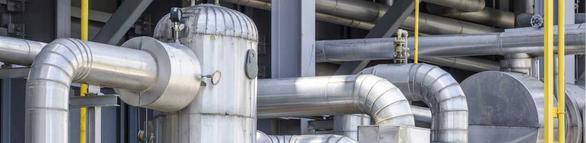
Duct Flow Meters for Air & Gas
Rheotherm flow sensing probes for duct gases are easy to install and provide long-term service with little or no maintenance. The output can be in mass, standard volume or velocity units. Options for hazardous locations (intrinsically safe/explosion-proof) are available.
 What Can We Measure?
Air and most other non-condensing gases, including corrosive and explosive gases. The stainless steel construction and lack of moving parts make it ideal for rugged industrial environments. Common uses include vent air, stack gas and digester gas. The application section has a complete list of fluids. Contact Us about any application you have or use the form on this page.
How Are They Installed?
These are insertion probe flow sensors that install through the pipe or duct wall. Typical line connections are 1” NPT, but flange, hot tap and sanitary fittings are available. The probes can be installed in horizontal or vertical pipes. With some models the electronics are integral to the sensor, and other models have a separate electronics enclosure to install, up to 200 feet from the sensor. Electronics Options
What Is the Turndown Ratio?
Typical calibration ranges are 10:1 (options up to 200:1), with good accuracy over the entire range. The sensors cannot be damaged by overranging.
 How Do They Work?
Our insertion flow sensors have a shaft with two stainless steel flow sensing tips. One tip has a heated RTD in it and the other an unheated RTD. The temperature differential between the two RTDs provides the primary flow signal. At high flow rates, flow removes more heat resulting in a lower differential. At low flow rates, flow removes less heat so the differential is higher. Nothing touches the gas but the metal probe. More on Method of Operation (PDF)
What If There Is Little to No Straight Run Available?
The historically reliable Rheotherm flow meter for duct flow measurement is available with a revolutionary sensor head which eliminates off-axis error common to other sensors. The system measures true mass flow rate in turbulent ducts and pipes using our standard gas flow probe design with the Rheovec sensor head added. Rheovec literature (PDF)
How Do I Get A Duct Flow Meter?
Contact one of our flow application specialists using the form on this page to configure a Rheotherm flow meter tailored to your application duct flow meters air and gas RFQ. You can also download and complete the Flow Application Data Sheet and email it to us at sales-flow@bionetics.com.
For other questions and ways to reach us, visit our Contact Us page for telephone, fax and email information.
- No moving parts
- Advanced signal processing electronics
- Field adjustable
- Maintenance-free
- Easy installation
- Choice of wetted materials
- Long-term reliability
| Standard | Options | |
| Service | Duct & pipe gases | |
| Pipe Sizes | 1” and larger pipes | |
| Wetted Surface | 316 SS | Hastelloy C-276®; Monel® |
| Flow Velocity Limits | 25-25,000 SFPM (0.127-127 meter/sec.) |
Consult Factory |
| Turndown Ratio | 10:1 | Up to 200:1 |
| Accuracy | +/- 1% of reading | |
| Repeatability | +/- 0.5% | |
| Max. Temperature | 175 ºF (80 ºC) | Up to 500 ºF (260 ºC) |
| Max. Pressure | Depends on Fitting | Up to 4,000 PSI |
| Standard | Options | |
| Process Connection | 1” MNPT | – Tri-Clover (Sanitary); – SS Flange; – Ball valve/hot tap; Most other fittings available |
| Outputs | 4 – 20 mA (flow rate) or Serial Burst with Flow Rate, Totalizer, and Fluid Temperature | – 0 – 10 or 0 – 5 VDC; – Pulse (5 VDC open collector); – HART (4-20 mA); – SPDT relay; – 4 to 20 mA temp |
| Enclosure | Integrated – NEMA 4X Cast Aluminum Remote – NEMA 4 |
Remote electronics: – 304 Stainless steel; – NEMA 7 Explosion-proof |
| Standard | Options | |
| Display | 2 X16 backlit LCD with selectable display of: – Mass/volume flow rate; – Temperature; – Total accumulated flow |
|
| Hazardous Environment | Integrated electronics: FM-Approved for: – Class I, Div. 1, Groups B,C,D; – Class I, Zone 1, IIB+H2 (US); – Class II, Div. 1, Groups E, F, G; – Class III, Div. 1 Remote electronics: Same as above except addition of Group A using ISB |
|
| Input Power | 24 VDC ±4V (200 mA; 300 mA w/display option) |
110/230 VAC ±10V |
Probe-type Sensor Flow Capacities for Gases
| VELOCITY LIMITS | ||
| feet/min | meter/sec | |
| Maximum | 25,000 | 127 |
| Minimum | 25 | 0.127 |


Contact Bionetics